|
By Eric Leung This is the procedure that I used for my 1978 308 GTS. The procedure should be the same in general for all 308s. Click on any picture to enlarge it. PARTS Here are the minimum of parts you should replace:
I ended up buying a 308 clutch kit from AW Import Parts in NJ. The kit had most of the pieces and it was cheaper than going piecemeal. It included the pressure plate, friction disc, O-rings and throwout bearing. The pressure plate and friction disc in this kit are made AP and the throwout bearing is made by Breda Lorett in Italy. Those who are offended by these manufacturers should probably purchase their parts from another source. In addition, since you will be draining the gearbox, you will need at least 5 quarts of suitable gearbox oil. TOOLS and SUPPLIES Besides needing a "normal" assortment of typical hand tools like wrenches and sockets, you will need:
PROCEDURE
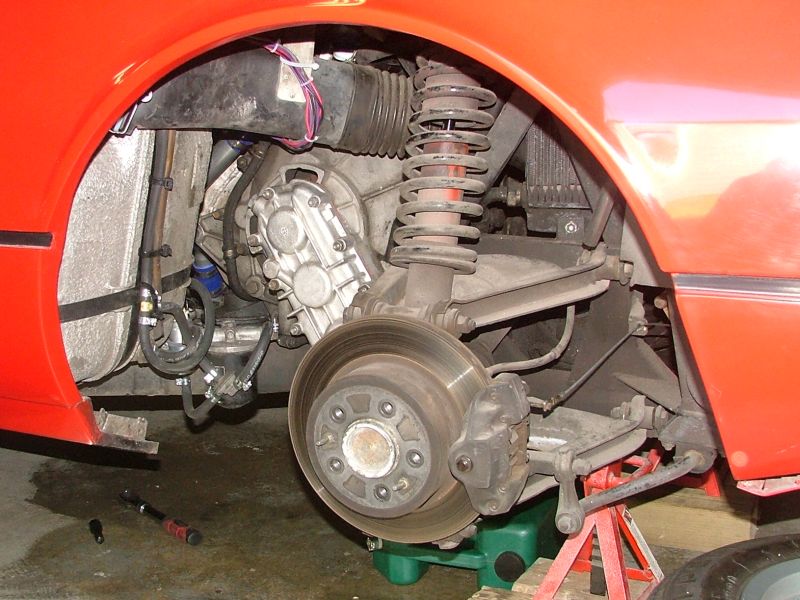
To have clear access to the bellhousing, you will need to remove the plastic duct going to the oil cooler. This is held on by a single bolt at the top of the metal bracket riveted to the duct. On carb cars, you will also need to remove the fuel filter from the mounting bracket. There is no need to remove the fuel lines, but you do need to get the filter housing out of the way to remove the bellhousing.
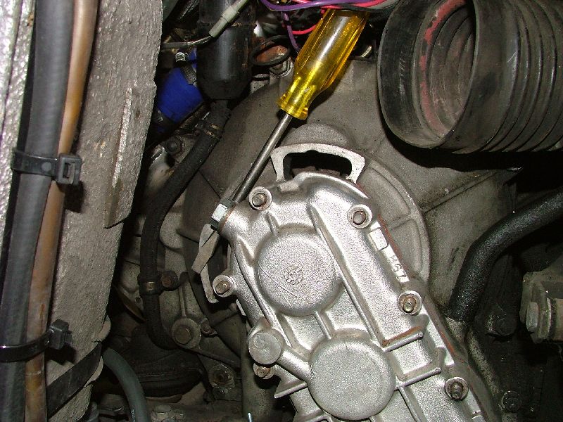
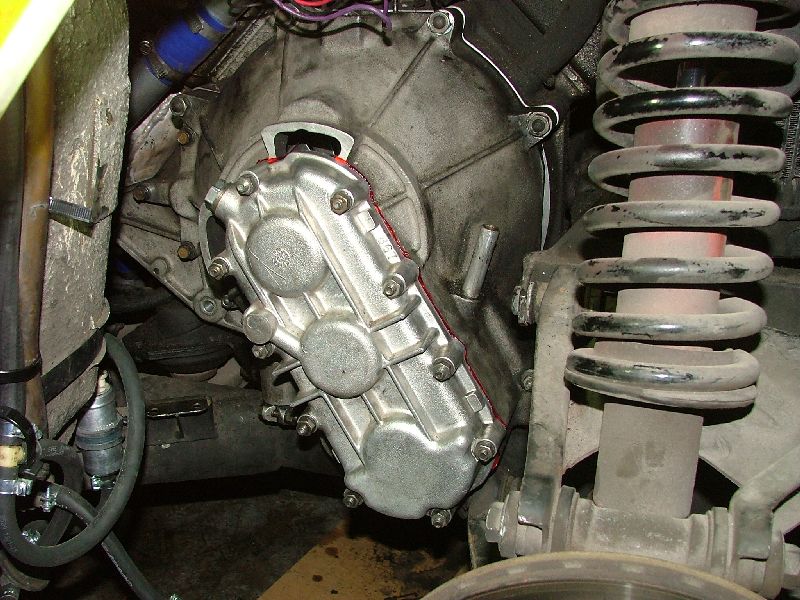
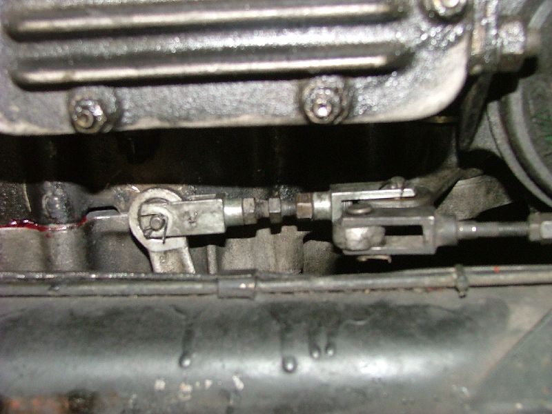
This photo shows the clutch linkage pivot arm and the two pivot pins that need to be removed. The lower one connects the arm to the clutch cable and the middle one (shown disconnected) is connected to a short turnbuckle. This, in turn, is connected to an arm on the bottom of the bellhousing. Each pin is secured with a cotter pin. It's easier at this point to disconnect as much as possible. After removing the two pivot pins, remove the linkage arm by removing the large pivot bolt holding the arm to the bellhousing. Drain the oil from the gearbox and the transfer case. Rather than copying the procedure into this document, you can read how to do it from this article on Birdman's website. Remove the ten nuts holding the transfer case cover. The transfer case cover will be sealed to the bellhousing, and it will require a bit of force (not a lot, but a bit) to remove. I used a large screwdriver as a lever between the bellhousing and the filler plug to break the seal. Once loose, it easily slid off the mounting studs.
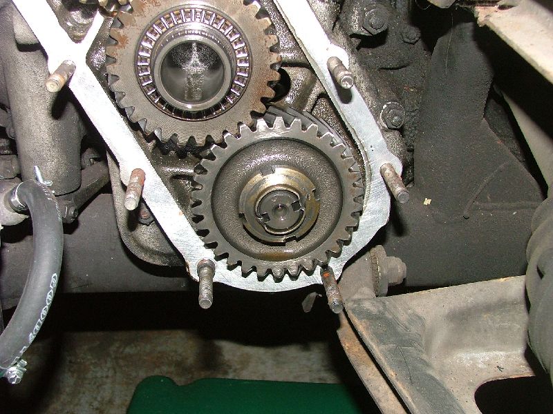
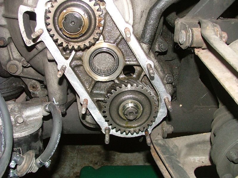
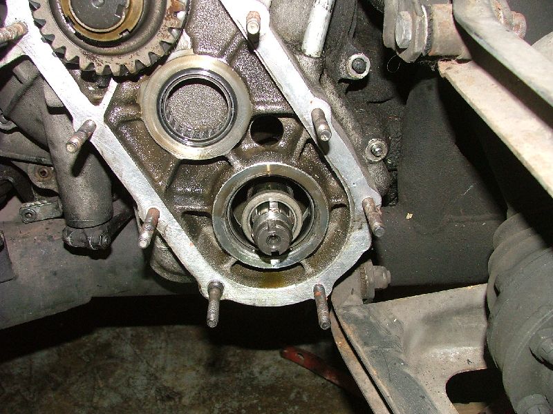
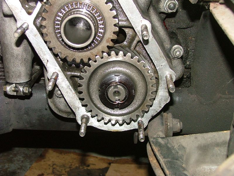
Once the cover is removed, the drop gears are exposed. You will be removing the lower and middle gear. The top gear does not need to be removed. As you can see in the photo, the sides of the ring nut are peened inward to lock the nut in place. You will need to use a small punch to bend the sides of the ring nut back out so you can loosen it.
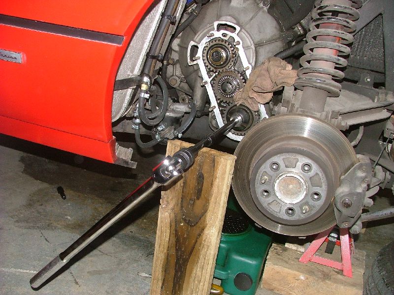
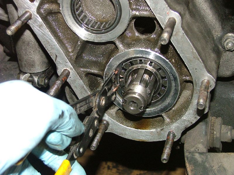
Here's how I set things up to remove the ring nut. The nut is torqued pretty tight so I needed a way to get enough leverage to loosen it. I used my long breaker bar, a long extension, the special Baum ring nut socket (#FR-102 from the Baum Tools Ferrari catalog) and a piece of wood with a notch in it to support the free end of the extension. To keep the engine from turning, I stuffed a shop towel between the gears and the ring nut easily loosened up.
When the ring nut is loose, you can remove the shop towel and remove the center gear. Be careful as there are thrust bearings on both sides of the gear. The gear should slide out very easily. Make note of which side is facing out. My gear was engraved with the transmission number on the inner surface.
The lower gear should just slide off the shaft. Mine was not stuck and I was able to get it off without a gear puller. Just like the middle gear, the inner surface of the lower gear was engraved with the transmission number.
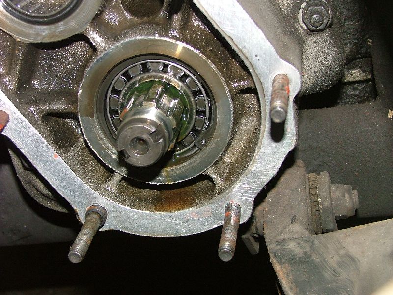
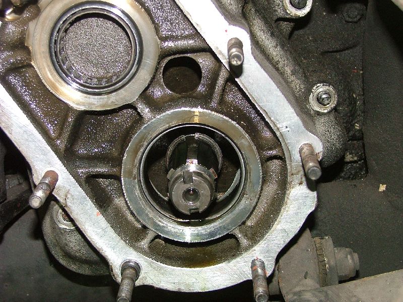
Behind the lower gear is a bearing which is held in by an internal snap ring. Use a pair of snap ring pliers to remove the snap ring. The bearing may or may not slide out easily. If it doesn't come out right away, don't worry about it just yet. When the bellhousing is loosened and pulled away from the engine, the bearing will slide out. There are two sizes of nuts and bolts holding the bellhousing onto the back of the engine. Remove all the hardware, including the crankcase breather tube and the gearbox breather tube.
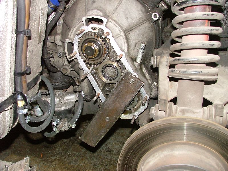
Once the bellhousing is loose, you will need to break the seal between it and the engine. I made a puller from a piece of scrap steel. Two of the transfer case cover studs are in line with the transmission input shaft. I drilled two holes in the scrap piece to fit the two studs and was able to just get the nuts back on with the puller in place. By slowly tightening the nuts, the bellhousing broke the seal and pulled away. After the bellhousing moved away from the engine about 1", I remove the puller and did the rest by hand.
By gently moving the bellhousing in and out, the lower bearing walked out on the input shaft and I was able to remove it.
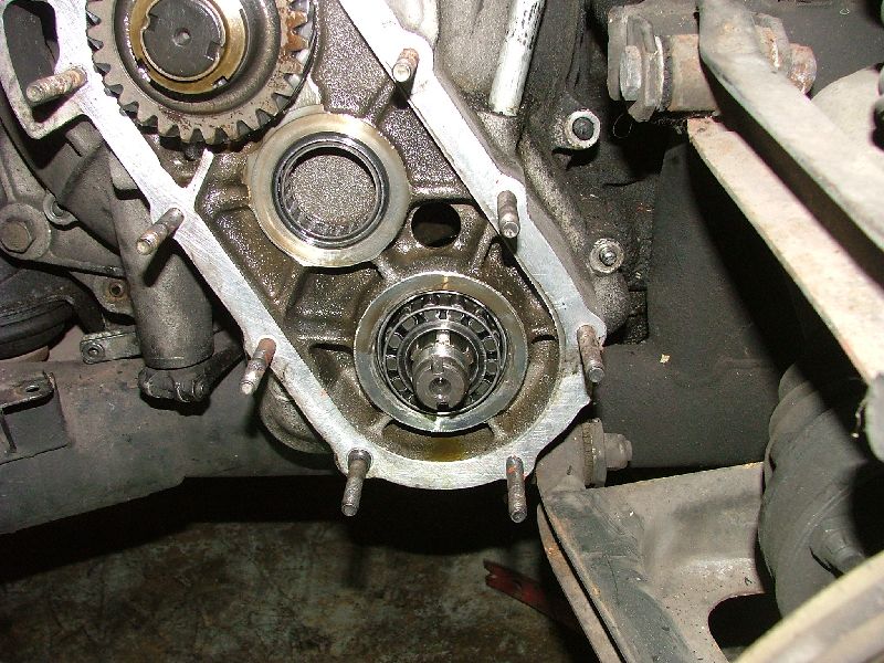
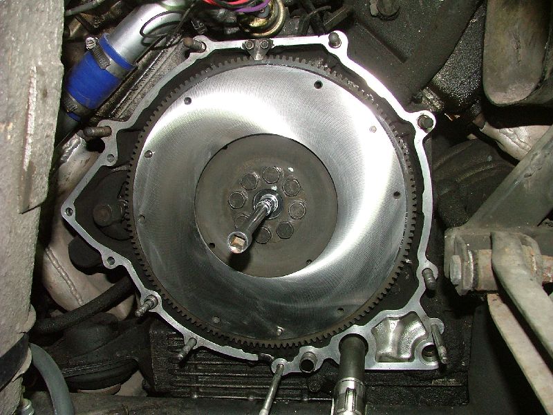
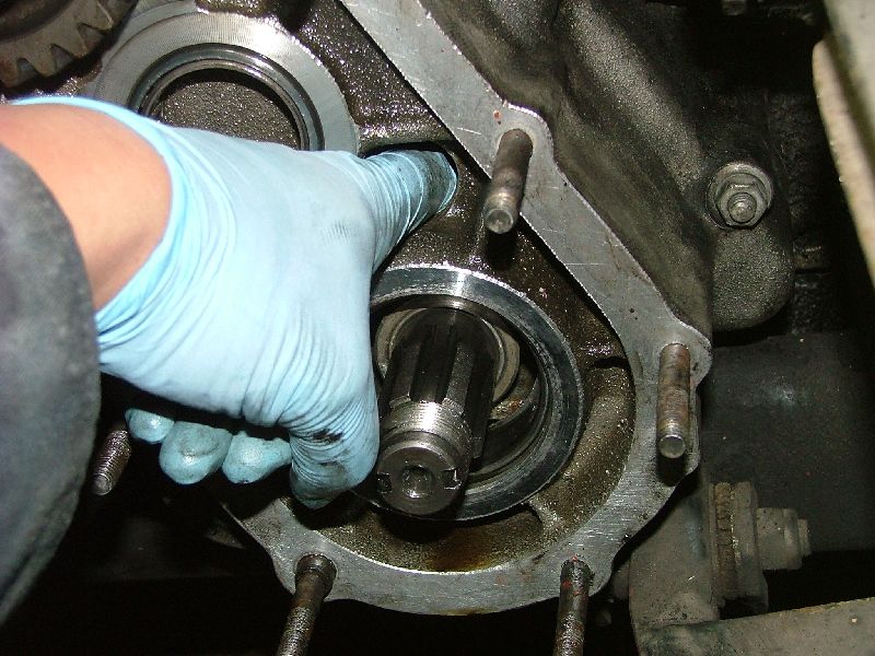
Once the bearing is removed, pull out the stepped spacer to expose the inner external snap ring. Use a pair of expanding snap ring pliers to remove this ring. This is very important as you will not be able to remove the bellhousing without removing this inner ring. Grab the bellhousing with both hands and carefully slide it straight out off the mounting studs and the transmission shaft. You will need to do a little maneuvering to get the bellhousing past the suspension components. It is heavy and the space is tight so be careful! With the bellhousing out of the way, you have clear access to the pressure plate. The pressure plate is held onto the flywheel with six fairly small bolts. I used an air impact hammer to remove the bolts and the engine did not rotate. If needed, you can put a ratchet with the 36mm socket on the crankshaft nose and jamb it against the rear suspension a-arm to keep the engine from turning. In addition to the six bolts, the pressure plate is held on to three locator pins on the flywheel. A little prying with a screwdriver will separate the pressure plate from the flywheel. The friction disc will come out along with the pressure plate.
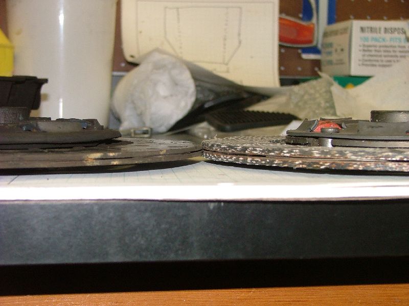
As you can see from this picture of a new friction disc compare to my old one, my clutch was definitely worn out.
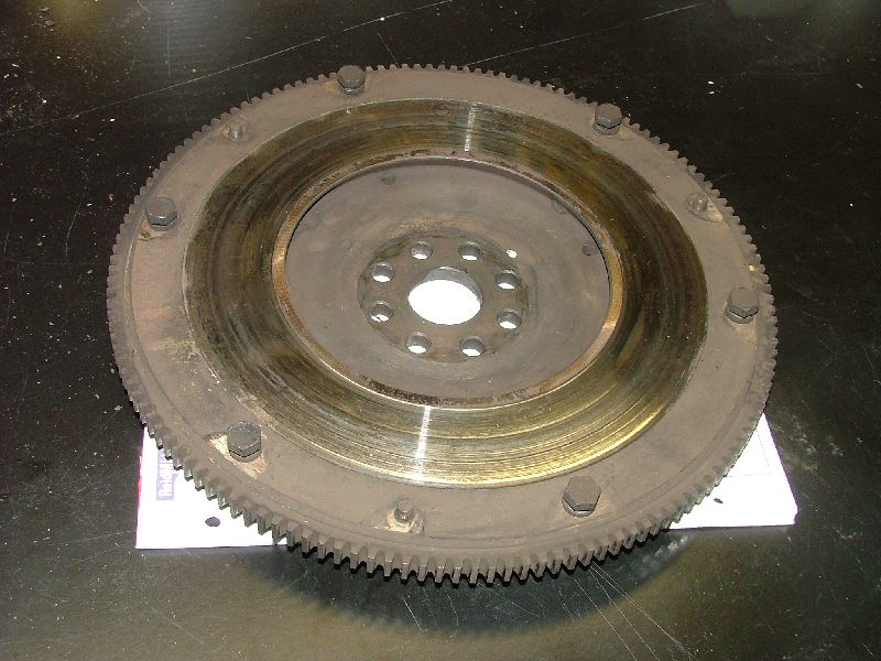
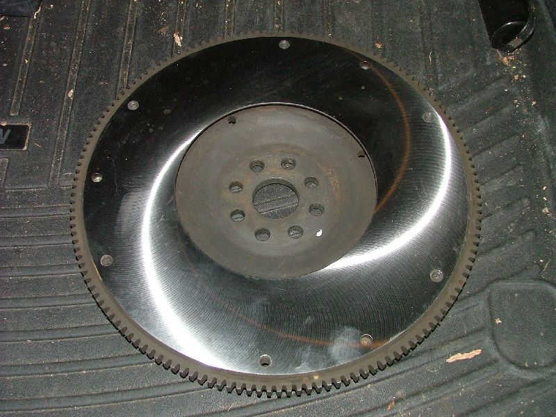
My flywheel was in pretty rough shape so I decided to get it resurfaced. To be sure I put the flywheel back on in the same orientation, I turned the engine to the 1-2 timing mark before loosening the flywheel bolts. This was actually not necessary since the holes are drilled slightly offset so the flywheel only goes on in one orientation. These bolts are really tight and I needed to use the breaker bar, long extension and block of wood trick again.
There is nothing too special about the flywheel and any competent machine shop can resurface it. I took mine to a local shop and $60 later, it looked great. There's nothing quite like a freshly machined surface. Make sure you get the locating pins back from the machine shop! My pilot bearing seemed in pretty good shape. However, since I had a new bearing, it was cheap insurance to just replace it.
There are various tricks to removing a pilot bearing. I've heard people have had success using grease and even wet paper. After trying (and failing) at using the grease trick, I used a slide puller instead. If you're feeling adventurous, have a look at this video to try the wet paper technique: Once the old bearing is out, smear a very light layer of grease on the outside of the new bearing and then put it in place. Using a hammer and a brass drift, gently tap the outer edge of the bearing until it is fully seated. While the flywheel is off is the perfect time to replace your crankshaft rear seal if it is leaking. Mine was not leaking and I decided not to replace it. Put the flywheel onto the end of the crankshaft and line up whatever marks you made. It actually only goes on one way as the holes are drilled slightly off. Make sure you put the spacer plate on before the bolts go back in. Also, clean off the bolts and use some red loctite on the threads. You don't want the flywheel bolts to loosen. Torque these bolts to 62 lbs-ft using a cross pattern. To keep the engine from turning, I used a ratchet with a 36mm socket on the crankshaft nose and jammed the handle against the passenger's side suspension arm.
I didn't have the use of a clutch alignment tool, so I used the next best thing. My 10mm deep socket was just slightly smaller than the pilot bearing hole. This socket with a 6� extension turned out to be a good clutch support/alignment tool. First, I used a clean rag and some lacquer thinner to clean off the contact surface on the flywheel and the pressure plate. Then I put the socket and extension into the pilot bearing.
The friction disc goes on next. It goes in a certain direction, with the larger side of the hub facing outward. Some discs are labeled with which side is which, but mine was not. Just pay attention because it really only works in one direction. Also, be careful to keep your greasy hands off the friction surface.
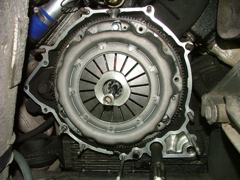
After the disc comes the pressure plate. The orientation does not matter so long as the holes line up. The pressure plate is heavy and you'll be glad the socket extension is there to support the plate as you line up the guide pins to the holes. Once the plate is on the pins, screw in the bolts loosely to hold the plate. When all the bolts are in, remove the socket.
Even without a proper alignment tool, it's pretty easy to line up the disc by just looking on the center hole. Tighten the pressure plate bolts a little and move the disc around until it looks completely centered in the hole. To make sure it was lined up, I put the bellhousing back on and could feel the output shaft engage correctly. I then pulled the bellhousing back off and torqued the pressure plate bolts to 18 lbs-ft.
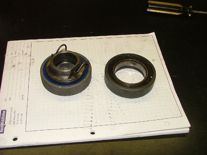
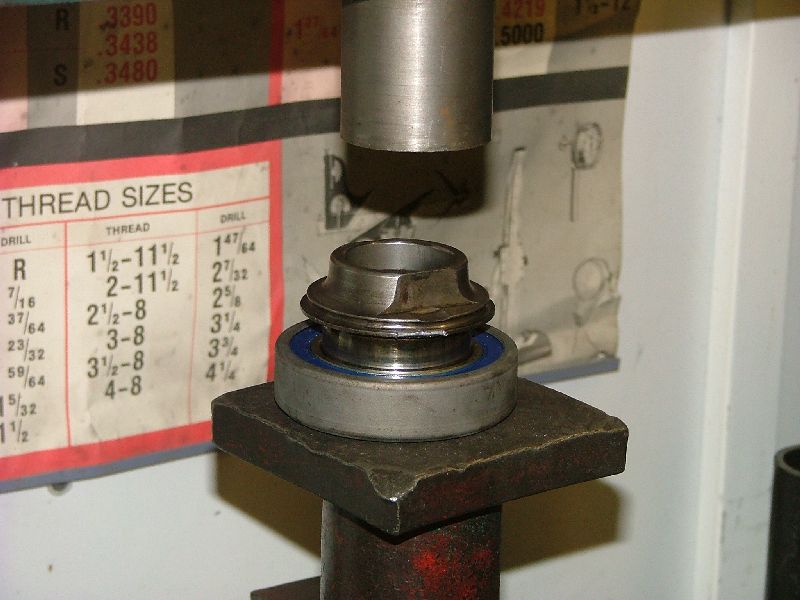
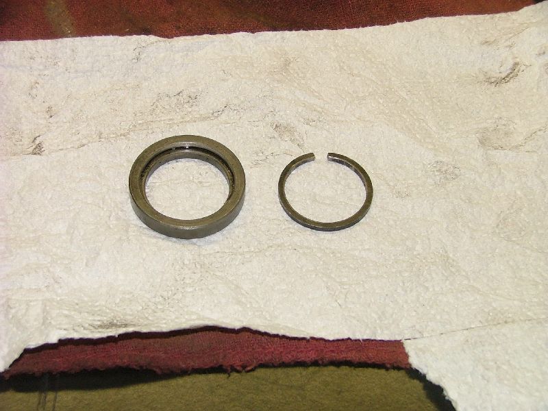
The throwout bearing is on the engine output shaft in the bellhousing. It should slide off the shaft easily. The bearing itself is pressed onto a carrier and you will need access to a hydraulic press. Clean all the old grease from the bearing carrier. Remove the retainer ring so it does not get damaged by the press.
Before pressing on the new bearing, make sure it is oriented the correct way. Press the assembly together then reattach the retaining ring.
Inside the carrier there is a groove. Fill this groove with high temp grease. Don't go overboard with this. Just use enough grease to fill the groove. I also put a little grease onto the end of the linkage fingers where they contact the throwout bearing.
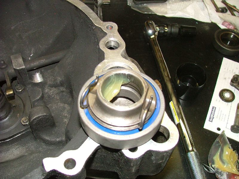
Slide the bearing assembly on the shaft in the bellhousing. Make sure the fingers on the release fork slide under the retaining clip. Wipe any excess grease off the shaft. The entire assembly should move smoothly with no rough spots or binding.
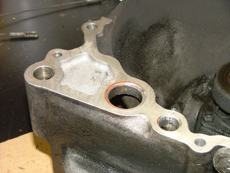
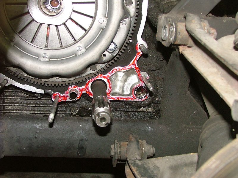
Using some suitable solvent and elbow grease, clean the mating surface on the bellhousing and the back of the engine. Make sure you get in all the nooks and crannies, especially the O-ring grooves.
There are three O-rings between the bellhousing and the engine. Two of the grooves are on the bellhousing side and one is on the engine side. Install the O-rings with a small dab of sealant to hold them in place.
Run a bead of sealant on the engine side mating surface. You only need to seal the lower right corner as this is the only place where gear oil passes. It's not necessary to seal completely around the bellhousing as it will only make disassembly more difficult next time. I used Loctite 518, an anerobic gasket eliminator.
Grab the bellhousing and carefully slide it into place. You need to be careful to not dislodge the O-rings. I put the bellhousing on and maneuvered it by hand until I could feel the output shaft engage in the clutch splines. Once it was on, I put the bellhousing nuts back on and slowly started tightening to pull the bellhousing toward the engine. While there was still some space between the engine and bellhousing, I crawled back under the car to make sure the O-rings were still in place. Remember that one of the bellhousing nuts holds the crankcase breather.
If all is well, tighten all the bellhousing nuts and bolts. The large fasteners are torqued to 40 lbs-ft and the small ones are torqued to 18 lbs-ft. Install the inner snap ring first, then the stepped collar, with the step toward the snap ring. When installed correctly, the inner snap ring will sit inside the step of the collar.
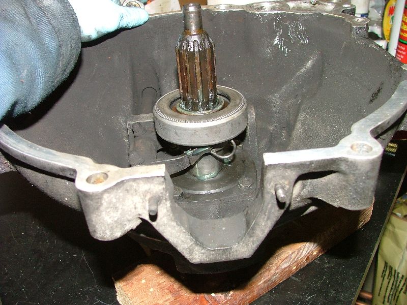
Using snap ring pliers, put the snap ring onto the transmission shaft and slide it into place in the groove. Make sure it's fully seated, then slide on the stepped collar. I was able to get the collar to seat correctly by lightly tapping on it with a small ball peen hammer and a brass drift. After tapping all around the collar, I could feel it seat correctly onto the snap ring. A simple way to check is to stick your finger into the hole above the shaft. You should be able to feel the snap ring seated into the back of the collar.
When the collar is in place, slide the lower bearing back on. You may need to tap lightly on the inner race to get it go in completely. You know it's in far enough when the outer snap ring groove is exposed. Using a pair of snap ring pliers, install the outer snap ring.
Making sure the gears are facing the correct way, slide the lower gear onto the transmission input shaft and the middle gear in the transfer case. My gears were engraved the transmission number on the inner surfaces so I knew which side faced out. Put the new lower ring nut on and torque to 145 lbs-ft. I used the long extension and block of wood trick again, but this time with a torque wrench. The crankshaft still had the ratchet attached to keep the engine from turning so I did not need to stuff a rag in the gears again.
Once torqued, the lower ring nut needs to be peened on the sides to lock it in place. I did this using a hammer and flat chisel, peening to the grooves on the sides of the transmission input shaft.
As with the bellhousing, clean off any old sealant on the mating surfaces of the transfer case cover. Run a bead of Loctite 518 on the bellhousing side of the transfer case and install the cover. Torque all the nuts to 18 lbs-ft.
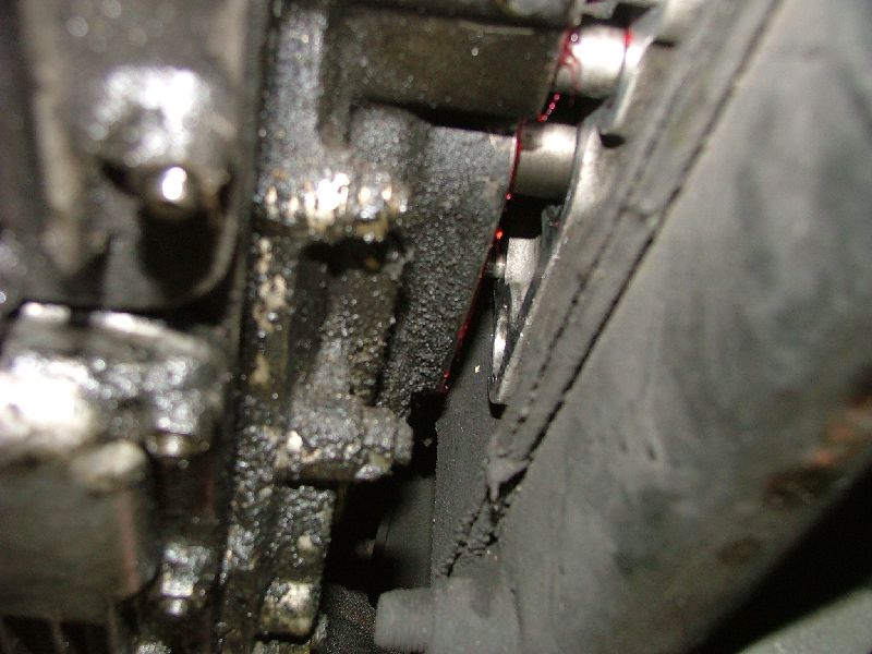
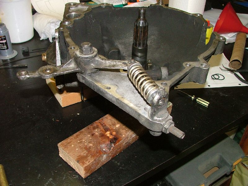
Clean all old grease off the clutch linkage arm and spring. Clean it all up and re-lube with a thin coat of grease. Crawl under the car and mount the arm using the large bolt to the bellhousing. Here is a picture of how it is mounted to the front of the bellhousing. Make sure it is oriented the correct way. I could not find a torque spec in the manual but based on the bolt size, I used 40 lbs-ft.
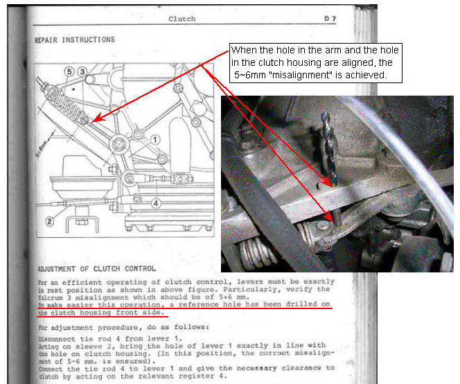
I used the following procedure, taken from a post by Steve Magnusson on F-chat on adjusting the clutch linkage. This basically involves inserting a drill bit into the linkage to hold it in place while while adjusting the turnbuckles to get the correct alignment. The original post is here:
After the clutch linkage arm is adjusted per the above procedure, attach the clutch cable to the bottom of the linkage arm using the clevis pin and cotter pin. Loosen the turnbuckle on the clutch cable and adjust it until there is 15-20 mm of free play at the clutch pedal. Put the transfer case and gearbox drain plugs back in and follow the second half of the procedure listed on Birdman's website to fill the gearbox. Check for leaks. If there aren't any, attach the breather hoses, fuel filter, oil cooler air duct and anything else that was removed in step #4. |
|
|